
A Hydrogen Fuel Cell uses oxygen from the air to generate electrical energy from the chemical energy stored in hydrogen, while generating a chemical product (water). The process differs from a combustion engine in that the primary conversion is from chemical energy directly to electrical energy, rather than heat, while heat is also generated as a by-product:
2H2(g) + O2(g) ⇒ 2H2O(l) + Electrical Energy + Heat
Fuel cell devices are designed to perform this reaction effectively while harnessing the electrical energy output. The device technology is developed at several levels described below.
The fuel cell is configured to separate the two input gases and directs them separately to anode (hydrogen) and cathode (air) electrodes to generate an electrical potential from which a current can be drawn:
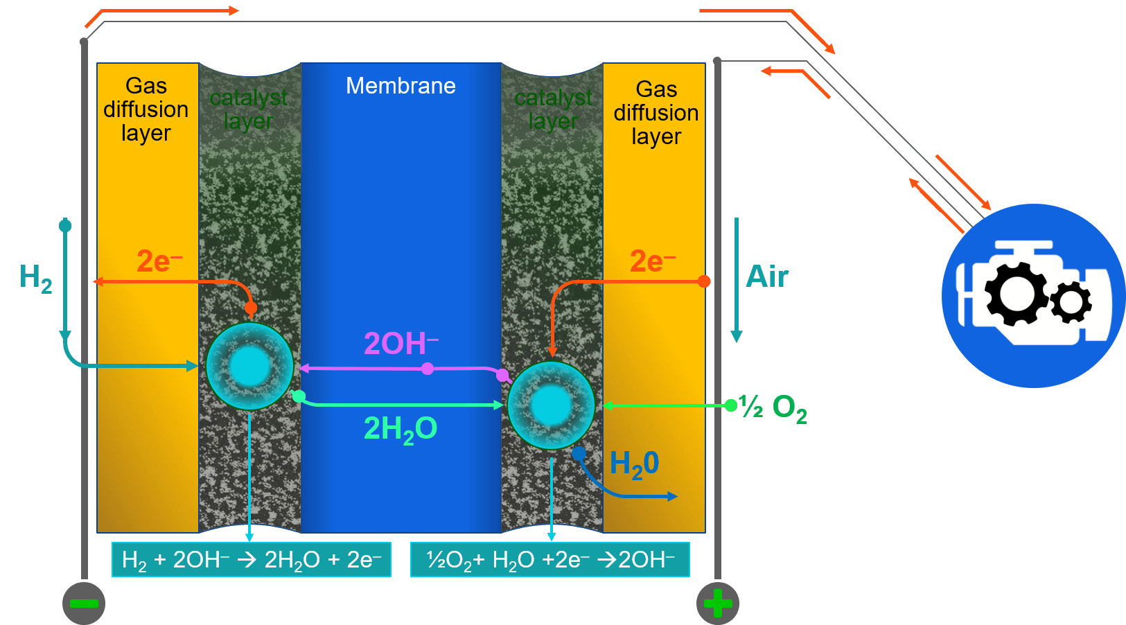
Components, layout and operating principle of an AEM Fuel Cell. AEM-Anion Exchange Membrane
Each electrode normally consists of 2 layers: a gas diffusion layer (GDL) and a catalyst layer, placed on either side of the Anion exchange membrane (AEM) at the heart of the device. These combined 5 layers are referred to as the Membrane-Electrode Assembly (MEA). Conductive current collectors placed against the two sides of the MEA are normally metallic plates, and these are inscribed with hollow channels called flow fields, through which the reacting gases are introduced to the cell, and the product water removed.
A series of individual cells are combined to increase device power output. This device is called the Fuel Cell Stack. In the fuel cell stack, the cells are generally connected electrically in series, while the reactant and product flows are supplied to the cells via manifolds connecting the cells in parallel.
The fuel cell MEA and stack are the core technologies that HYDROLITE has developed and demonstrated up to 5 kW of gross power output. Further scaling is a simple matter of adding more cells to the stack assembly.
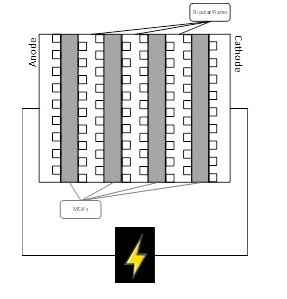
Diagram of a hydrogen Fuel Cell Stack showing the MEA’s stacked in series between
bipolar plates that serve as current collectors and reactant/product distributers
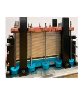 Example HYDROLITE assembled stack
In addition to the fuel cell stack, a hydrogen-to-power system includes electrical, thermal and fluidic control subsystems and an electronic interface to generate standalone power delivery that must be tailored to the size of the fuel cell stack. HYDROLITE is currently deploying a 5kW delivery system to serve as a first AEM device platform. Such a system can then also be scaled/redesigned to control a fuel cell stack or module of arbitrary size.
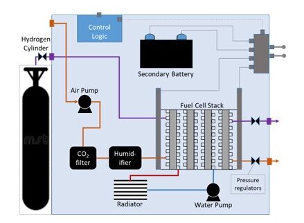
The AEM Fuel Cell Balance of Plant –
Including the fuel cell stack, reactant supply, exhaust systems,
cooling loop, battery, control logic, and power management
Multiple critical materials cost drivers are eliminated with HYDROLITE AEM Device Technology, while retaining the performance advantages of exchange membrane fuel cells. Our technology is set to help enable the rapid emergence of a Hydrogen Economy towards deep decarbonization over the coming decades.